# VESTA-028
DIO-52-B
## DI/DO Module
## Introduction
DIO-52-B is a DI/DO module that integrates wired devices into wireless networks to create automated responses and enhances security and convenience.
The DI/DO module has built-in Digital Input and Digital Output terminals. It can be connected to a single sensor, switch, or device to receive an on/off command from the Control Panel via DO and return the current status via DI to the Panel.
The DIO-52-B can also be connected to separate devices. With the Home Automation rule set in the Panel, the device connected to its DI point can be turned into the trigger of events, and its DO point into the responder of events. When “Input Follower Mode” is selected in the Control Panel, the DO terminal is interconnected to the DI terminal, and the DO terminal device will be activated by the DI terminal device trigger.
## **Parts Identification**
1. **Test Button**
Press once to send a learn code to the Control Panel.
2. **LED indicator**
The LED indicator lights up in the following conditions:
* Flashes 6 times:
When the Input terminal is triggered or when the Switch is transmitting a signal.
* Flashes 3 times:
When the Output Terminal is triggered.
* Flashes once every 4 seconds:
The batteries are extremely low and need to be replaced.
3. **Battery Compartment**
4. **Power Terminal**
5. **Digital Input (DI) Terminal**
6. **Digital Output (DO) Terminal**
* When connecting wire to each terminal, please use a mini Phillips screwdriver to screwn/unscrew the terminal. Avoid using a flathead screwdriver, which may cause scrapes.
7. **Mounting Holes**
8. **Strain Relief Clamps**
The clamps are used for securing the wires and providing strain relief to protect the wires from metal cutout.
9. **Wiring Holes**
## Features
### ***Power Supply***
**AC Power and Battery**
* DIO-52-B can be powered by a two-wired 5-12V DC adapter when connected to the Power Terminal, or it can be battery-powered by three CR123 Lithium batteries.
* When the Power Terminal and batteries are both in use, DIO-52-B will only power through the adaptor.
### **Low Battery Detection**
* DIO-52-B features a Low Battery Detection function. When the battery voltage is low, DIO-52-B will transmit a Low Battery signal to notify the user. When changing batteries, after removing the old batteries, press the Test Button twice to discharge fully before inserting new batteries.
### ***Supervision***
DIO-52-B will transmit a supervision signal every 30 to 50 minutes to report its condition.
### *Getting Started*
1. Insert batteries or connect the two-wired 5-12V DC adapter to power on DIO-52-B.
2. Put the Control Panel into Learning Mode; refer to the Control Panel manual for details.
3. Press the Test button once, the LED will flash 6 times.
4. If the Control Panel receives the signal, it will display the information accordingly, refer to Control Panel manual to complete the learning process.
{% hint style="warning" %}
Note:
When learnt into the Control Panel, the DIO-52-B will be recognized as 2 separate devices (DI & DO), occupying 2 zones in the Panel.
{% endhint %}
### ***Walk Test***
* After the DIO-52-B is learnt-in, put the Control Panel into (**Walk Test**) mode, hold the DI/DO module in the desired location, and press the Test Button to transmit a test signal to the Control Panel. If the Control Panel is within the DIO-52-B signal range, the panel will display DI\&DO information accordingly.
* Proceed with mounting and installation once you are satisfied that the DI/DO module functions properly in the desired location.
### ***Operation Mode***
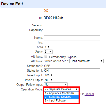
The DI/DO module can operate according to different modes selected on the Control Panel webpage or Home Portal Server (the Mode selection function is not available in Vesta SmartHomeSec App). Please select the mode in the **DO Device Edit** page.
| **Control Panel webpage** | **Home Portal Server** |
| ------------------------------------------------------------------------------------------------------------------------------------------------------------------------------------------------------ | ------------------------------------------------------------------------------------------------------------------------------------------------------------------------------------------------------ |
| | |
### **Appliance Control:**
When DIO-52-B is used for appliance control, the input and output terminals are connected to the same device, e.g. a water valve.
The output terminal is used to receive an on/off signal from the Control Panel to turn/on off the connected device, while the input terminal is used to transmit the current status of the connected device to the Panel.
When the “Appliance Control” mode is selected, you can remotely turn on/off the connected device from the Control Panel webpage, Home Portal Server, or Vesta Home 5 App, but the output following the input setting in DO will be deactivated. You can program Home Automation rules, Scenes on the Panel webpage or Home Portal Server to integrate the device connected to DIO-52-B with other devices in the Control Panel.
Example of DI/DO practice for Appliance Control:

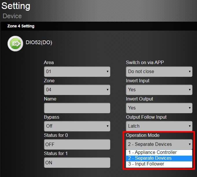
### **Separate Devices:**
In this mode, the input and output terminals of DIO-52-B are connected to separate devices. The input terminal is used to monitor the activation of the connected device and transmit the trigger signal to the Control Panel. The output terminal is used to receive on/off signal from the Control Panel to turn/on off the connected device.
When DIO-52-B is working in this mode, the output follows the input setting in DO is deactivated. Users can program Home Automation rules, Scenes on Panel webpage or Home Portal Server to turn the DI point into a trigger of events and the DO point into a responder of events.
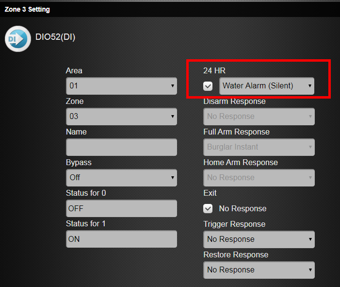
Example of DI/DO practice for Separate Devices:
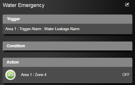
DI input terminal is connected to a water leakage sensor, and the DO output is connected to a water valve. By setting a Home Automation rule on HPS, the Panel will automatically turn off the water valve when the water leakage sensor is triggered.
| **DI settings** | **DO settings** |
| ------------------------------------------------------------------------------------------------------------------------------------------------------------------------------------------------------ | ------------------------------------------------------------------------------------------------------------------------------------------------------------------------------------------------------ |
| | |
| **Home Automation rule** |
| ------------------------------------------------------------------------------------------------------------------------------------------------------------------------------------------------------ |
| |

### **Input Follower:**
In this mode, the input and output terminals of DIO-52-B are connected to separate devices. The output terminal device is interconnected with the input terminal device.
When the input terminal device is triggered, the output terminal device will activate according to the Output Follow Input setting. Please refer to the below section ***DI and DO Settings*** for details.
After the “Input Follower” mode is selected, the Home Automation Rule & Apply Scene function on the Home Portal Server will be deactivated. You will need to program the **Output Follow Input** setting on the DO Device Edit page so that the output terminal device will activate accordingly following the trigger of the input terminal device.
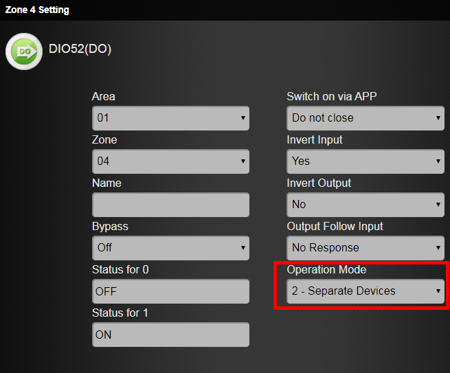
Example of DI/DO practice for Input Follower:
After selecting the “Input Follower” mode on the DO device edit page, select “Latch” for the Output Follow Input setting. The output terminal device will be activated instantly when the input terminal device is triggered.


## ***DI and DO Settings***
### **Output Terminal (DO):**
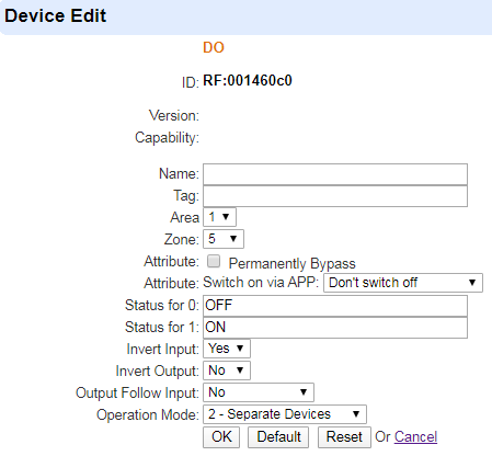
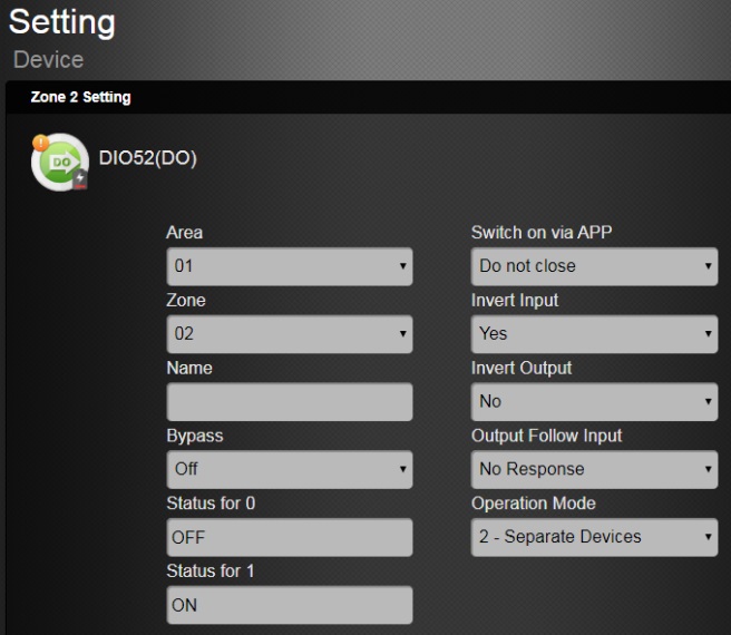
Program the DO settings in **DO Device Edit** page on Panel webpage or Home Portal server.
| **Control Panel webpage** | **Home Portal Server** |
| ------------------------------------------------------------------------------------------------------------------------------------------------------------------------------------------------------- | -------------------------------------------------------------------------------------------------------------------------------------------------------------------------------------------------------- |
| | |
Switch on via APP:
* **Do nothing** – The Do output device cannot be switched on via the app.
* **Don’t switch off** - The Do output device will not switch off after being switched on via the app.
* **Switch off after 1-240 sec/5-30 min** – After being switched on via APP for the selected time, the Do output device will switch off.
Status for 0: Enter the Status 0 description for the Output terminal.
Status for 1: Enter the Status 1 description for the Output terminal.
Invert Input: Select to change the order of Status 0 and Status 1 for DI input. When “Yes” is selected, the order of Status 0 and Status 1 for DI input will be changed.
Invert Output: Select to change the order of Status 0 and Status 1 for DO output. When “Yes” is selected, the order of Status 0 and Status 1 for DO output will be changed.
Output Follows Input: This function is available only when Operation Mode "3-Input Follower" is selected.
* **No** - When the input terminal device is triggered, the output terminal device will not be activated.
* **Latch** - The output terminal device will be activated instantly when the input terminal device is triggered.
* **On for 10-240 sec/5-30 min** - When the input terminal device is triggered, the output terminal device will be activated for a set duration.
Operation Mode: Select the Operation Mode for DIO-52-B. Please refer to the previous section for details.
### **Input Terminal (DI):**
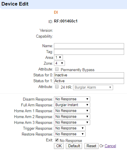
Program the DI settings in the **DI Device Edit** page on the Panel webpage or Home Portal server.
| **Control Panel webpage** | **Home Portal Server** |
| ------------------------------------------------------------------------------------------------------------------------------------------------------------------------------------------------------- | ------------------------------------------------------------------------------------------------------------------------------------------------------------------------------------------------------- |
| | |
Status for 0: Enter the Status 0 description for the Input terminal.
Status for 1: Enter the Status 1 description for the Input terminal.
## Installation
DIO-52-B can be deployed on a flat surface or mounted on the wall. After you have finished the walk test, and you are satisfied that the device is able to communicate with the control panel in the chosen location, proceed with installation.
1. Disconnect the main power supply.
2. Loosen the bottom fixing screw and remove the top cover of DIO-52-B.
3. Use the holes on the base to mark the mounting location on the wall.
4. Drill holes into marked location and insert wall plugs if required, screw the base onto the mounting location.
5. Replace the top cover and tighten the bottom fixing screw.
---
# Agent Instructions: Querying This Documentation
If you need additional information that is not directly available in this page, you can query the documentation dynamically by asking a question.
Perform an HTTP GET request on the current page URL with the `ask` query parameter:
```
GET https://vesta-guide.gitbook.io/vesta-guide/vesta-028.md?ask=
```
The question should be specific, self-contained, and written in natural language.
The response will contain a direct answer to the question and relevant excerpts and sources from the documentation.
Use this mechanism when the answer is not explicitly present in the current page, you need clarification or additional context, or you want to retrieve related documentation sections.


 |
|  |
### **Appliance Control:**
When DIO-52-B is used for appliance control, the input and output terminals are connected to the same device, e.g. a water valve.
The output terminal is used to receive an on/off signal from the Control Panel to turn/on off the connected device, while the input terminal is used to transmit the current status of the connected device to the Panel.
When the “Appliance Control” mode is selected, you can remotely turn on/off the connected device from the Control Panel webpage, Home Portal Server, or Vesta Home 5 App, but the output following the input setting in DO will be deactivated. You can program Home Automation rules, Scenes on the Panel webpage or Home Portal Server to integrate the device connected to DIO-52-B with other devices in the Control Panel.
|
### **Appliance Control:**
When DIO-52-B is used for appliance control, the input and output terminals are connected to the same device, e.g. a water valve.
The output terminal is used to receive an on/off signal from the Control Panel to turn/on off the connected device, while the input terminal is used to transmit the current status of the connected device to the Panel.
When the “Appliance Control” mode is selected, you can remotely turn on/off the connected device from the Control Panel webpage, Home Portal Server, or Vesta Home 5 App, but the output following the input setting in DO will be deactivated. You can program Home Automation rules, Scenes on the Panel webpage or Home Portal Server to integrate the device connected to DIO-52-B with other devices in the Control Panel.

 |
|  |
| **Home Automation rule** |
| ------------------------------------------------------------------------------------------------------------------------------------------------------------------------------------------------------ |
|
|
| **Home Automation rule** |
| ------------------------------------------------------------------------------------------------------------------------------------------------------------------------------------------------------ |
|  |

### **Input Follower:**
In this mode, the input and output terminals of DIO-52-B are connected to separate devices. The output terminal device is interconnected with the input terminal device.
When the input terminal device is triggered, the output terminal device will activate according to the Output Follow Input setting. Please refer to the below section ***DI and DO Settings*** for details.
After the “Input Follower” mode is selected, the Home Automation Rule & Apply Scene function on the Home Portal Server will be deactivated. You will need to program the **Output Follow Input** setting on the DO Device Edit page so that the output terminal device will activate accordingly following the trigger of the input terminal device.
Example of DI/DO practice for Input Follower:
After selecting the “Input Follower” mode on the DO device edit page, select “Latch” for the Output Follow Input setting. The output terminal device will be activated instantly when the input terminal device is triggered.


## ***DI and DO Settings***
### **Output Terminal (DO):**
Program the DO settings in **DO Device Edit** page on Panel webpage or Home Portal server.
| **Control Panel webpage** | **Home Portal Server** |
| ------------------------------------------------------------------------------------------------------------------------------------------------------------------------------------------------------- | -------------------------------------------------------------------------------------------------------------------------------------------------------------------------------------------------------- |
|
|

### **Input Follower:**
In this mode, the input and output terminals of DIO-52-B are connected to separate devices. The output terminal device is interconnected with the input terminal device.
When the input terminal device is triggered, the output terminal device will activate according to the Output Follow Input setting. Please refer to the below section ***DI and DO Settings*** for details.
After the “Input Follower” mode is selected, the Home Automation Rule & Apply Scene function on the Home Portal Server will be deactivated. You will need to program the **Output Follow Input** setting on the DO Device Edit page so that the output terminal device will activate accordingly following the trigger of the input terminal device.
Example of DI/DO practice for Input Follower:
After selecting the “Input Follower” mode on the DO device edit page, select “Latch” for the Output Follow Input setting. The output terminal device will be activated instantly when the input terminal device is triggered.


## ***DI and DO Settings***
### **Output Terminal (DO):**
Program the DO settings in **DO Device Edit** page on Panel webpage or Home Portal server.
| **Control Panel webpage** | **Home Portal Server** |
| ------------------------------------------------------------------------------------------------------------------------------------------------------------------------------------------------------- | -------------------------------------------------------------------------------------------------------------------------------------------------------------------------------------------------------- |
|  |
|  |
Switch on via APP:
* **Do nothing** – The Do output device cannot be switched on via the app.
* **Don’t switch off** - The Do output device will not switch off after being switched on via the app.
* **Switch off after 1-240 sec/5-30 min** – After being switched on via APP for the selected time, the Do output device will switch off.
Status for 0: Enter the Status 0 description for the Output terminal.
Status for 1: Enter the Status 1 description for the Output terminal.
Invert Input: Select to change the order of Status 0 and Status 1 for DI input. When “Yes” is selected, the order of Status 0 and Status 1 for DI input will be changed.
Invert Output: Select to change the order of Status 0 and Status 1 for DO output. When “Yes” is selected, the order of Status 0 and Status 1 for DO output will be changed.
Output Follows Input: This function is available only when Operation Mode "3-Input Follower" is selected.
* **No** - When the input terminal device is triggered, the output terminal device will not be activated.
* **Latch** - The output terminal device will be activated instantly when the input terminal device is triggered.
* **On for 10-240 sec/5-30 min** - When the input terminal device is triggered, the output terminal device will be activated for a set duration.
Operation Mode: Select the Operation Mode for DIO-52-B. Please refer to the previous section for details.
### **Input Terminal (DI):**
Program the DI settings in the **DI Device Edit** page on the Panel webpage or Home Portal server.
| **Control Panel webpage** | **Home Portal Server** |
| ------------------------------------------------------------------------------------------------------------------------------------------------------------------------------------------------------- | ------------------------------------------------------------------------------------------------------------------------------------------------------------------------------------------------------- |
|
|
Switch on via APP:
* **Do nothing** – The Do output device cannot be switched on via the app.
* **Don’t switch off** - The Do output device will not switch off after being switched on via the app.
* **Switch off after 1-240 sec/5-30 min** – After being switched on via APP for the selected time, the Do output device will switch off.
Status for 0: Enter the Status 0 description for the Output terminal.
Status for 1: Enter the Status 1 description for the Output terminal.
Invert Input: Select to change the order of Status 0 and Status 1 for DI input. When “Yes” is selected, the order of Status 0 and Status 1 for DI input will be changed.
Invert Output: Select to change the order of Status 0 and Status 1 for DO output. When “Yes” is selected, the order of Status 0 and Status 1 for DO output will be changed.
Output Follows Input: This function is available only when Operation Mode "3-Input Follower" is selected.
* **No** - When the input terminal device is triggered, the output terminal device will not be activated.
* **Latch** - The output terminal device will be activated instantly when the input terminal device is triggered.
* **On for 10-240 sec/5-30 min** - When the input terminal device is triggered, the output terminal device will be activated for a set duration.
Operation Mode: Select the Operation Mode for DIO-52-B. Please refer to the previous section for details.
### **Input Terminal (DI):**
Program the DI settings in the **DI Device Edit** page on the Panel webpage or Home Portal server.
| **Control Panel webpage** | **Home Portal Server** |
| ------------------------------------------------------------------------------------------------------------------------------------------------------------------------------------------------------- | ------------------------------------------------------------------------------------------------------------------------------------------------------------------------------------------------------- |
|  |
| 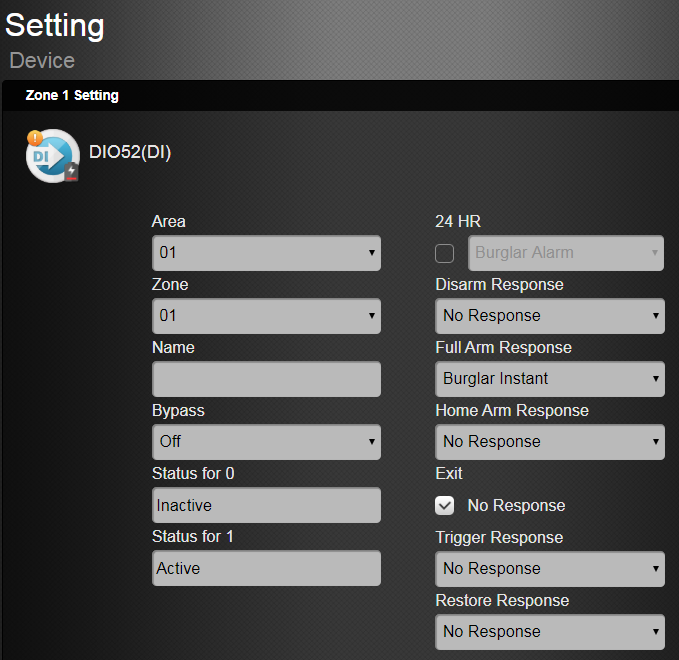 |
Status for 0: Enter the Status 0 description for the Input terminal.
Status for 1: Enter the Status 1 description for the Input terminal.
## Installation
DIO-52-B can be deployed on a flat surface or mounted on the wall. After you have finished the walk test, and you are satisfied that the device is able to communicate with the control panel in the chosen location, proceed with installation.
1. Disconnect the main power supply.
2. Loosen the bottom fixing screw and remove the top cover of DIO-52-B.
3. Use the holes on the base to mark the mounting location on the wall.
4. Drill holes into marked location and insert wall plugs if required, screw the base onto the mounting location.
5. Replace the top cover and tighten the bottom fixing screw.
---
# Agent Instructions: Querying This Documentation
If you need additional information that is not directly available in this page, you can query the documentation dynamically by asking a question.
Perform an HTTP GET request on the current page URL with the `ask` query parameter:
```
GET https://vesta-guide.gitbook.io/vesta-guide/vesta-028.md?ask=
|
Status for 0: Enter the Status 0 description for the Input terminal.
Status for 1: Enter the Status 1 description for the Input terminal.
## Installation
DIO-52-B can be deployed on a flat surface or mounted on the wall. After you have finished the walk test, and you are satisfied that the device is able to communicate with the control panel in the chosen location, proceed with installation.
1. Disconnect the main power supply.
2. Loosen the bottom fixing screw and remove the top cover of DIO-52-B.
3. Use the holes on the base to mark the mounting location on the wall.
4. Drill holes into marked location and insert wall plugs if required, screw the base onto the mounting location.
5. Replace the top cover and tighten the bottom fixing screw.
---
# Agent Instructions: Querying This Documentation
If you need additional information that is not directly available in this page, you can query the documentation dynamically by asking a question.
Perform an HTTP GET request on the current page URL with the `ask` query parameter:
```
GET https://vesta-guide.gitbook.io/vesta-guide/vesta-028.md?ask=