VESTA-068N/VESTA-067
VESTA-068N/VESTA-067
Insert SIM and External Battery

External Battery 7.5V /400Ah/3000W
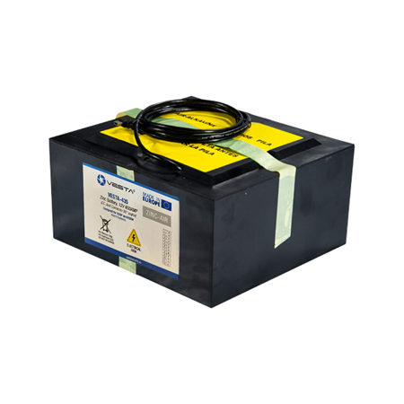
External Battery 12V/500Ah, 6000W
APN configuration on the panel
Enable cloud when using the panel with batteries only
| Step 1: Log in as an installer in the SmartHomeSec APP | ||
Step 2: Select the + button (Add panel) | ||
| Step 3: Enter the panel's MAC address found on a label |
| Step 1: Access the panel as installers, the default code is [7982] | ||
| Step 2: Select the Main system menu section | ||
| Step 3: Select account list | ||
| Step 4: Select add | ||
| Step 5: If it's a new user: Select create an account | ||
Step 6: Fill in the user data for APP access |
Installer -> Settings
Installer -> Settings -> Devices
Botón learn de los dispositivos VESTA
| Ajustes -> Panel | ||
| Ajustes -> Panel -> Seguridad | ||
|
| Ajustes -> Panel | ||
| Ajustes -> Panel -> Panel | ||
| NOTAS ANEXO 1 |
| Instalador -> Ajustes | ||
| Ajustes -> PIN de usuario | ||
| Añadir el Nombre y código para cada usuario, este código permitirá al usuario cambiar de modo desde la APP o teclados consultar Manual de usuario para más información |
| Ajustes -> Panel | ||
| Panel -> Actualización de FW | ||
| Seleccionar del listado el firmware con versión más alta (Número más alto y letra más alta) |
| Ajustes -> Reporte | ||
| En el apartado reporte disponemos de configuración de reporte para eventos y archivos capturados para fotos de PIRCAMS | ||
| En este apartado configuramos la URL de repote de nuestra CRA, y muy importante el GRUPO 2 o superior ya que el gruopo 1 está empleado para la APP. ANEXO 2 para ejemplos |
| Ajustes -> Reporte | ||
| En el apartado reporte disponemos de configuración de reporte para eventos y archivos capturados para fotos de PIRCAMS | ||
| En este apartado configuramos la URL de repote de nuestra CRA para el envío de fotos. ANEXO 3 para ejmplos |
Example