# VESTA-181
**PRL-1ZBS(R)-AC**
## **ZigBee Relay Toggle Switch**
## **Introduction**
PRL-1ZBS is a ZigBee Relay Toggle Switch. The Relay Toggle Switch can be connected to wired device and set to either Normal Open (N.O.) or Normal Close (N.C.) status. After joining ZigBee network, the Relay Toggle Switch can be controlled via ZigBee network to activate connected devices.
The Relay Toggle Switch utilizes ZigBee technology for wireless signal transmission. ZigBee is a wireless communication protocol that is reliable, has low power consumption and has high transmission efficiency. Based on the IEEE802.15.4 standard, ZigBee allows a large amount of devices to be included in a network and coordinated for data exchange and signal transmission.
The Relay Toggle Switch serves as an end device in the ZigBee network. It can be included in the ZigBee network to transmit or receive signal, but cannot permit any other ZigBee device to join the network through the Relay Toggle Switch.
Models with router function also serve as a router in the ZigBee network. After being included in the ZigBee network, it allows other ZigBee device to join the network through the Power Switch.
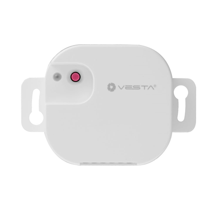
## **Parts Identification**

1. **LED indicator**
The LED indicator is used to indicate Relay status:
1. Flashes once: The Relay has reset.
2. Flashes twice: The Relay has successfully joined a ZigBee network.
3. Flashes once every 20 minutes: The Relay has lost connection to its current ZigBee network.
2. **Function Button**
The function button is used to reset the Relay Toggle Switch to join an available ZigBee network.
Press and hold the button for 10 seconds then release to reset the Relay Toggle Switch.
### **Connection Terminals**
Press the button to open the clipper for each terminal and connect wiring. Release the button to close the clipper and hold wire in place.
3. **Reserved**
4. **Line (AC input)**
5. **Neutral**
6. **NO**
For Normal Open connection with the device
7. **Common**
8. **NC**
For Normal Close connection with the device
## **Specification**
* Power Source (External Power): 100-240VAC
* Relay Output: Potential-free SPDT relay, Maximum Operation Load: 5A (Resistive) at 24VDC or 240VAC
* Stranded Wire: 16-26 AWG
* Operating Temperature: -10°C to 45°C (14°F to 113°F)
* Humidity: Up to 85% non-condensing
* Dimension: 71.1mm x 49mm x 26mm
## **Installation Environment**
The Relay Controller should be installed indoors in a dry location.
* It is recommended to install the device in a fire resistant plastic gangbox.
* Do not install the device in a metal gangbox for optimization of RF range.
## **Caution**
* All works on the device, including installation and maintenance, must be performed by a qualified and licensed electrician.
* To prevent electrical shock and/or equipment damage, disconnect electrical power at the main fuse or circuit breaker before installation and maintenance.
* Do not connect the device to loads exceeding supported load current.
## **Installation**

The insertion holes’ wiring specification is AWG 16-26 or Ø 1.31-0.129 (mm²).
Wire the Relay according to the instructions below or refer to the diagram for more information.
1. Please turn off the power supply before connection.
2. Connect the L and N terminals of the power supply to the Line and Neutral terminals of PRL respectively.
3. Depend on the device you wish to control via the Relay, select NO or NC terminal and wire the Relay with the device to establish Normal Open or Normal Close connection with device.
4. After completing the wiring, turn on the power supply to power on the Relay Toggle Switch.
{% hint style="info" %}
*\*
Wiring of the PRL should only be performed by certified technician with proper knowledge and training in electric equipment.
{% endhint %}
## **ZigBee Network Setup**
### ***ZigBee Device Guideline***
ZigBee is a wireless communication protocol that is reliable, has low power consumption and has high transmission efficiency. Based on the IEEE802.15.4 standard, ZigBee allows a large amount of devices to be included in a network and are coordinated for data exchange and signal transmission.
### ***Joining the ZigBee Network***
As a ZigBee device, the Relay needs to join a ZigBee network to receive commands. Please follow the steps bellow to join the Relay into a ZigBee network.
1. Connect the power input to the Relay Toggle Switch according to Installation instruction above and power up the Relay Toggle Switch.
2. Press and hold the function button for 10 seconds as the Relay resets and starts searching for existing ZigBee network. Please make sure the permit-to-join feature on the router or coordinator of your ZigBee network is enabled.
3. If the Relay Toggle Switch successfully joins a ZigBee network, the LED Indicator will flash twice to confirm.
4. After joining the ZigBee network, the Relay Toggle Switch will be registered in the network automatically. Please check the ZigBee network coordinator, system control panel or CIE (Control and Indicating Equipment) to confirm if joining and registration is successful.
5. After joining the ZigBee network, if the Relay Toggle Switch loses connection to the current ZigBee network, the LED indicator will flash every 20 minutes. Please check your ZigBee network condition and Relay Toggle Switch signal range to correct the condition.
### ***Removing Device from ZigBee Network (Factory Reset)***
To remove the Relay Toggle Switch from current ZigBee network, the device must be put to Factory Reset to complete device removal. Factory Reset function will clear the device of its stored setting and information and prompt the it to search for new ZigBee network.
**Before removing device, make sure the Relay Toggle Switch is within current ZigBee network signal range**
1. Press and hold the function button for 10 seconds, then release the button to reset Relay Toggle Switch.
2. Upon reset, the device will clear current ZigBee network setting and transmit signal to ZigBee coordinator to remove itself from current ZigBee network. It will then actively search for available ZigBee network again and join the network automatically.
### ***ZigBee Router Device Capacity (PRL-1ZBSR-AC Only)***
The Relay Toggle Switch model with Router function allows other ZigBee devices to join the ZigBee Network through the Router. It has maximum capacity of 40 devices/routers.
## **Operation**
## ***Relay Control***
After the Relay toggle Switch has successfully joined a ZigBee network, the coordinator/control panel can remotely control the Relay to turn On, Off or toggle between On and Off condition. Please refer to your ZigBee coordinator/control panel for detail.
## **Appendix (For developers only)**
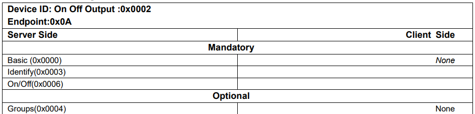
### ***Relay Cluster ID***
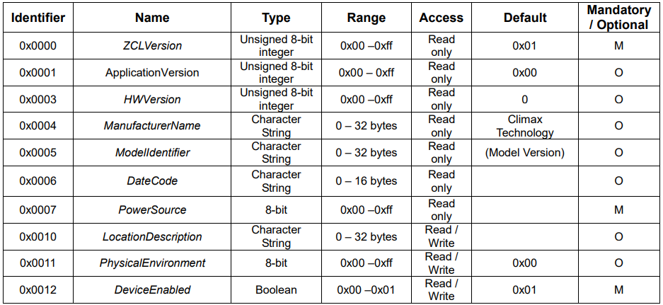
### Attribute of Basic Cluster Information
### Attribute of Identify Cluster Information
### ***Attribute of On/Off Cluster Information***
### ***Attributes of the Groups cluster Information***
 The Relay Controller should be installed indoors in a dry location.
* It is recommended to install the device in a fire resistant plastic gangbox.
* Do not install the device in a metal gangbox for optimization of RF range.
## **Caution**
The Relay Controller should be installed indoors in a dry location.
* It is recommended to install the device in a fire resistant plastic gangbox.
* Do not install the device in a metal gangbox for optimization of RF range.
## **Caution**  * All works on the device, including installation and maintenance, must be performed by a qualified and licensed electrician.
* To prevent electrical shock and/or equipment damage, disconnect electrical power at the main fuse or circuit breaker before installation and maintenance.
* Do not connect the device to loads exceeding supported load current.
## **Installation**

The insertion holes’ wiring specification is AWG 16-26 or Ø 1.31-0.129 (mm²).
Wire the Relay according to the instructions below or refer to the diagram for more information.
1. Please turn off the power supply before connection.
2. Connect the L and N terminals of the power supply to the Line and Neutral terminals of PRL respectively.
3. Depend on the device you wish to control via the Relay, select NO or NC terminal and wire the Relay with the device to establish Normal Open or Normal Close connection with device.
4. After completing the wiring, turn on the power supply to power on the Relay Toggle Switch.
{% hint style="info" %}
*\
* All works on the device, including installation and maintenance, must be performed by a qualified and licensed electrician.
* To prevent electrical shock and/or equipment damage, disconnect electrical power at the main fuse or circuit breaker before installation and maintenance.
* Do not connect the device to loads exceeding supported load current.
## **Installation**

The insertion holes’ wiring specification is AWG 16-26 or Ø 1.31-0.129 (mm²).
Wire the Relay according to the instructions below or refer to the diagram for more information.
1. Please turn off the power supply before connection.
2. Connect the L and N terminals of the power supply to the Line and Neutral terminals of PRL respectively.
3. Depend on the device you wish to control via the Relay, select NO or NC terminal and wire the Relay with the device to establish Normal Open or Normal Close connection with device.
4. After completing the wiring, turn on the power supply to power on the Relay Toggle Switch.
{% hint style="info" %}
*\